Overview
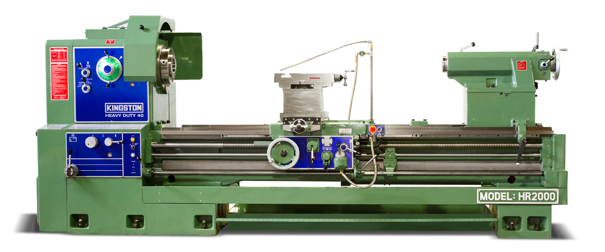
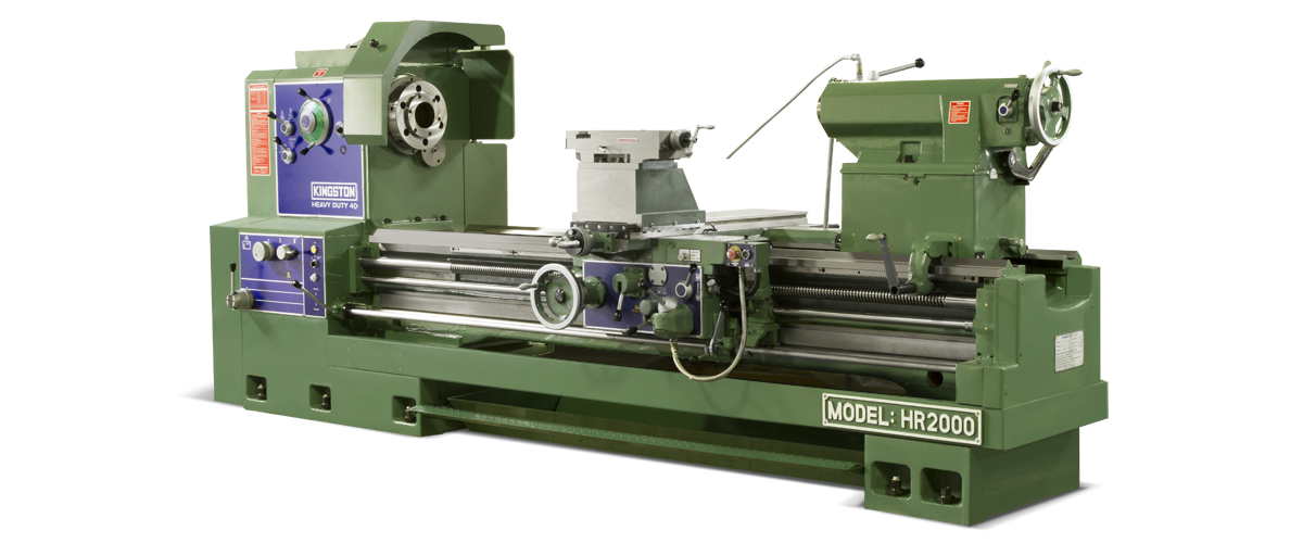
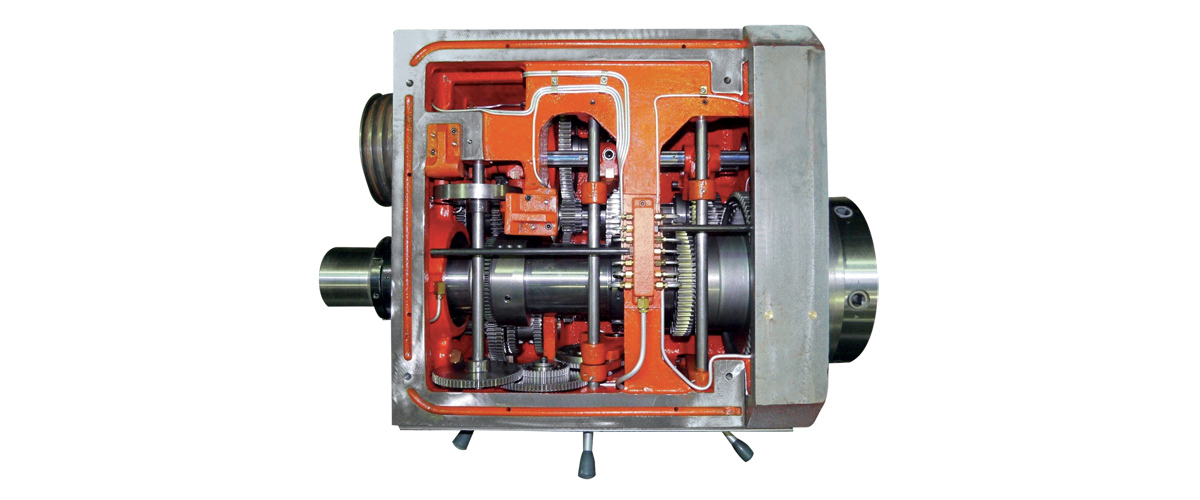
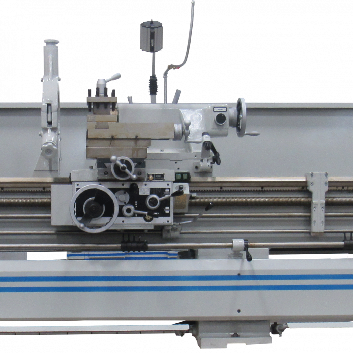
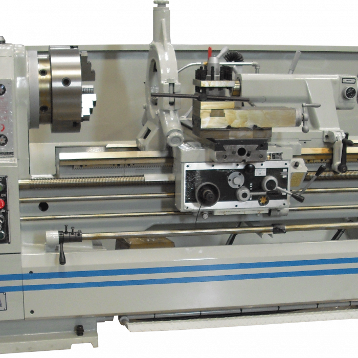
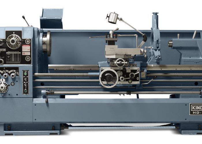
Known as “The Workhorse” in machine shops across the country, Kingston’s heavy-duty HR model has been the industry leader in its class for nearly 40 years. At the heart of this machine is a strong and rigid headstock with a hardened and ground main spindle, which features a 4.09” bore and a 3-point bearing support system for superior cutting capability. Operators benefit from the increased control that comes with 16 spindle speeds (8 – 800 RPM) and a wider range of feeds and threading choices. The unique rib structure of the 22” bedway is made with high-quality casting to ensure greater stability and accuracy in heavy-duty applications. The HR is available in 30”, 34”, or 40″ swing and lengths from 80” – 320”.
Standard Features
- 20 HP, 230V/460V, 3 Phase, 60 Cycle Motor, Switch & Wiring Complete
- 4.09” Spindle Bore
- Spindle Nose: D1-11 Camlock
- 16 Spindle Speeds: 8 – 800 RPM
- Headstock Spindle Adaptor: ASA-450 to MT#6
- 4-Way Rapid Traverse
- T-Slot on Tool Slide
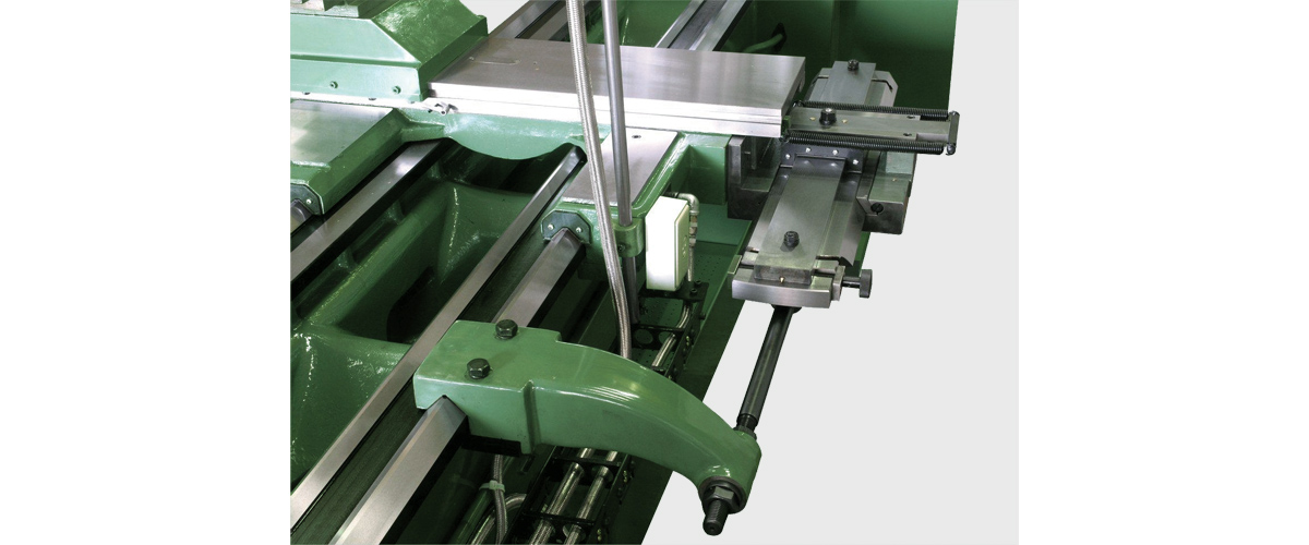
- Hardened and Ground Bed and Cross Slide Ways
- 2-Speed Drive Tailstock Quill
- Coolant System with Pump and Piping
- Pull Drawer Chip (Coolant) Pan
- Sliding Chuck Guard
Optional Accessories
- 11.9”, 19.7” Steady Rests with Roller Jaws
- 23.5” Steady Rest with Roller Jaws (34″ & 40” Swing Only)
- Roller Bracket
- 7.9” Follow Rest
- Telescopic Taper Attachment ±8° & 3.5”/foot, 19.7” Stroke
- Drilling Attachment
- Carriage Stops
- Low RPM Modification (0.4 – 40 RPM, Factory Install Only)
- Higher RPM Modification (12 – 1200 RPM, Factory Install Only)
- Hydraulic Brake System (Factory Install Only)
- Full-Length Splash Guard (Factory Install Only)
- Chip Conveyor (Factory Install Only)
- Digital Readout (DRO)
- Aloris Quick Change Tool Post & Sets
- 3-Jaw & 4-Jaw Manual Chucks
| Capacity | 30″ | 34″ | 40″ |
| Swing Over Bed | 30″ | 34″ | 40″ |
| Swing Over Cross Slide | 20.7” | 25.1” | 31.0” |
| Swing Over Gap (Up to C.C. 160˚ Only) | 41.2” | 45.6” | 51.5” |
| Distance Between Centers | 80” / 120” / 160” / 200” / 240” / 280” / 320” | 80” / 120” / 160” / 200” / 240” / 280” / 320” | 80” / 120” / 160” / 200” / 240” / 280” / 320” |
| Width of Bed | 22″ | 22″ | 22″ |
| Height from Floor to Work Center | 46.5” | 48.6” | 51.5″ |
| Headstock | 30″ | 34″ | 40″ |
| Spindle Bore | 4.09” | 4.09” | 4.09” |
| Taper of Spindle Bore & Center | ASA #450 x MT #6 | ASA #450 x MT #6 | ASA #450 x MT #6 |
| Spindle Nose | D1-11, opt. A1-11 | D1-11, opt. A1-11 | D1-11, opt. A1-11 |
| Number of Spindle Speed | 16 | 16 | 16 |
| Spindle Speed | 8 – 800 RPM, 12 –1200 RPM (Opt) | 8 – 800 RPM, 12 –1200 RPM (Opt) | 8 – 800 RPM, 12 –1200 RPM (Opt) |
| Gear Box | 30″ | 34″ | 40″ |
| Number of Feed Changes | Fine (20), Normal (40), Coarse (30) | Fine (20), Normal (40), Coarse (30) | Fine (20), Normal (40), Coarse (30) |
| Range of Long. Feeds per Rev. | 0.00048” – 0.0168”, 0.0024” – 0.0337”, 0.0384” – 0.2694” | 0.00048” – 0.0168”, 0.0024” – 0.0337”, 0.0384” – 0.2694” | 0.00048” – 0.0168”, 0.0024” – 0.0337”, 0.0384” – 0.2694” |
| Longitudinal Cross | ½ of Longitudinal Feed | ½ of Longitudinal Feed | ½ of Longitudinal Feed |
| Leadscrew Dia. & Threads per Inch | 1.9” 2 TPI (P=12 mm) | 1.9” 2 TPI (P=12 mm) | 1.875” 2 TPI (P=12 mm) |
| Threading range – Whitworth | 2 to 28 TPI (40) / Coarse 5/8” to 8” Pitch (16) | 2 to 28 TPI (40) / Coarse 5/8” to 8” Pitch (16) | 2 to 28 TPI (40) / Coarse 5/8” to 8” Pitch (16) |
| Threading range – Metric | 1 to 14 Pitch (31) / Coarse 16 to 200 mm Pitch (61) | 1 to 14 Pitch (31) / Coarse 16 to 200 mm Pitch (61) | 1 to 14 Pitch (31) / Coarse 16 to 200 mm Pitch (61) |
| Threading range – Module | 0.5 to 7 M (20) / Coarse 8 to 56 M (30) | 0.5 to 7 M (20) / Coarse 8 to 56 M (30) | 0.5 to 7 M (20) / Coarse 8 to 56 M (30) |
| Threading range – D.P. | 56 to 4 D.P (40) / Coarse 3.5” to .5” D.P. (30) | 56 to 4 D.P (40) / Coarse 3.5” to .5” D.P. (30) | 56 to 4 D.P (40) / Coarse 3.5” to .5” D.P. (30) |
| Tool Slide | 30″ | 34″ | 40″ |
| Maximum Travel of Compound | 9.4” | 9.4” | 9.4” |
| Maximum Travel of Cross Slide | 21.2” | 21.2” | 21.2” |
| Tailstock | 30″ | 34″ | 40″ |
| Tailstock Quill Travel | 11.8” | 11.8” | 11.8” |
| Tailstock Quill Diameter | 5.1” | 5.1” | 5.1” |
| Tailstock Center | M.T. #6 | M.T. #6 | M.T. #6 |
| Motor | 30″ | 34″ | 40″ |
| Main Drive Motor | 20 HP (15kw) | 20 HP (15kw) | 20 HP (15kw) |
| Coolant Pump Motor | 1/4 HP | 1/4 HP | 1/4 HP |
| Dimensions | 30″ | 34″ | 40″ |
| Floor Space (L x W) | 193” / 233” / 256” / 312” / 358” / 390” / 431” x 82″ | 193” / 233” / 256” / 312” / 358” / 390” / 431” x 82″ | 193” / 233” / 256” / 312” / 358” / 390” / 431” x 82″ |
| Weight (lbs) | 10,230 / 11,770 / 14,300 / 15,840 / 18,370 / 20,420 / 23,500 | 10,450 / 11,990 / 14,520 / 16,060 / 18,590 / 20,640 / 23,650 | 10,940 / 12,250 / 14,790 / 16,330 / 18,860 / 20,900 / 23,950 |
